
How to Calculate Gearbox Ratio and Output RPM
Industrial machinery requires specific rotational speeds to perform different operations. An electric motor may operate at 1440 RPM, while a conveyor drive pulley, crusher, or material-handling machine may require a much lower rotational speed. An industrial gearbox helps bridge this difference by reducing or adjusting the motor’s rotational speed while transmitting mechanical power.
Understanding how to calculate Gearbox Ratio is important for mechanical engineers, maintenance professionals, production managers, conveyor designers, and industrial buyers. A correctly calculated ratio helps determine the output speed required for a particular machine and provides a starting point for evaluating the appropriate gearbox.
However, selecting an industrial gearbox involves more than calculating RPM. Engineers must also consider output torque, motor power, load characteristics, gearbox efficiency, service factor, operating hours, and mounting arrangement.
For industrial conveyor applications, selecting the right SMSR Gearbox Manufacturer in Ahmedabad is an important part of evaluating suitable power transmission solutions.
This guide explains gearbox ratio calculations through standard engineering formulas, practical numerical examples, conveyor belt speed calculations, and industrial applications. It also examines the role of Shaft Mounted Speed Reducer (SMSR) gearboxes in suitable conveyor drive arrangements and introduces the relevant product range available from Nisuka Industries.
The objective is to help readers understand the calculations and make better-informed gearbox selection decisions.
What Is a Gearbox Ratio?
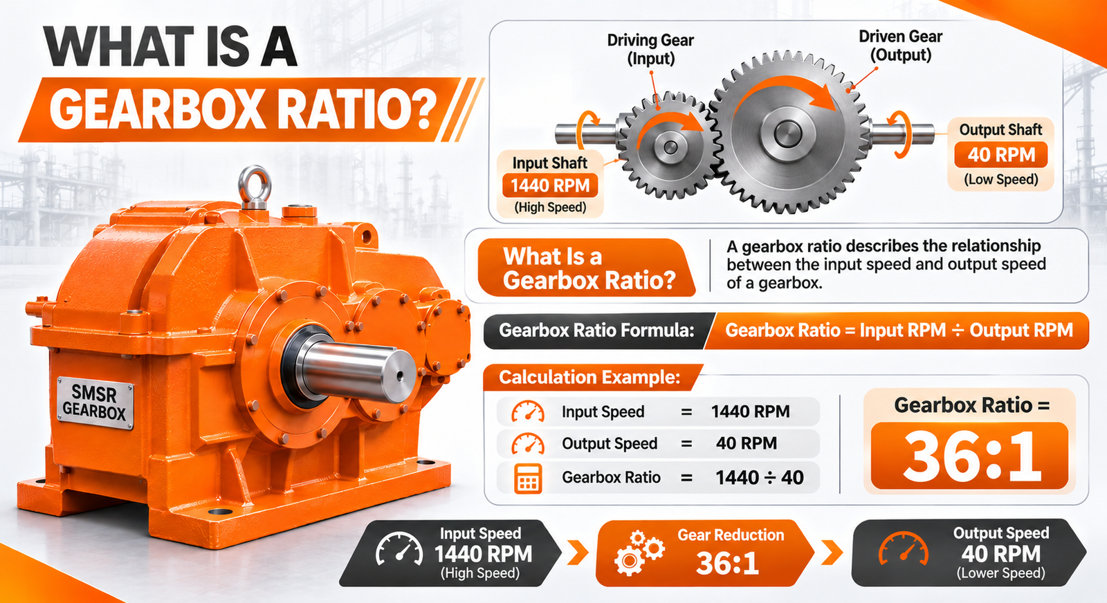
A gearbox ratio is the relationship between the rotational speed of the input shaft and the rotational speed of the output shaft.
In a conventional reduction gearbox, the output shaft rotates more slowly than the input shaft. The ratio indicates how many input shaft revolutions correspond to one output shaft revolution.
For example, a 10:1 reduction ratio means the input shaft completes approximately 10 revolutions for every one revolution of the output shaft.
The basic relationship is:
A gearbox ratio helps engineers determine the speed reduction required to match an electric motor with the operating speed of driven machinery.
Understanding Gear Reduction Ratio
The theoretical output speed is 72 RPM.
This reduction is useful when machinery requires slower rotation and increased available output torque.
Different gearbox designs use different internal gear arrangements. Therefore, the actual reduction ratio should always be taken from the manufacturer’s technical documentation rather than assumed from the gearbox’s external appearance.
Businesses looking for conveyor belt solutions can also explore Nisuka Industries as a Conveyor Rubber Belt Supplier for industrial material-handling requirements.
Why Gearbox Ratio Is Important in Industrial Applications
Industrial machinery operates under different speed and load requirements. A motor’s rotational speed may not directly match the operating requirements of the driven equipment.
A suitable gearbox ratio helps:
- Match motor speed with machine operating speed.
- Reduce rotational speed for conveyor applications.
- Increase available output torque.
- Control material movement.
- Support machinery operating under varying loads.
- Establish suitable power transmission arrangements.
For example, a conveyor transporting bulk materials may require a lower drive pulley speed than the connected motor. A reduction gearbox helps achieve the required speed relationship
What Is Input RPM and Output RPM?
RPM stands for Revolutions Per Minute. It measures the number of complete rotations made by a rotating shaft in one minute.
Both input RPM and output RPM are essential when performing gearbox speed calculations.
What Is Input RPM?
Input RPM refers to the rotational speed entering the gearbox through its input shaft.
In a typical industrial drive arrangement, an electric motor supplies rotational power to the gearbox.
For example, if a motor operates at 1440 RPM and is directly connected to the gearbox, the gearbox input speed is 1440 RPM.
The motor’s nameplate speed should be checked carefully because rated speed, synchronous speed, and actual operating speed are not necessarily identical.
What Is Output RPM?
Output RPM refers to the rotational speed delivered by the gearbox to the driven equipment.
The output speed depends on the input speed and the actual reduction ratio.
For example, a gearbox receiving 1440 RPM with a 15:1 reduction ratio produces a theoretical output speed of 96 RPM.
The output shaft may drive a conveyor pulley, processing machine, or another compatible industrial component.
What Is the Gearbox Ratio Formula?
The standard Gearbox Ratio Formula for a reduction gearbox is:
Where:
- i = Gearbox reduction ratio.
- Nin = Input rotational speed in RPM.
- Nout = Output rotational speed in RPM.
The result is generally expressed as 10:1, 15:1, or 20:1.
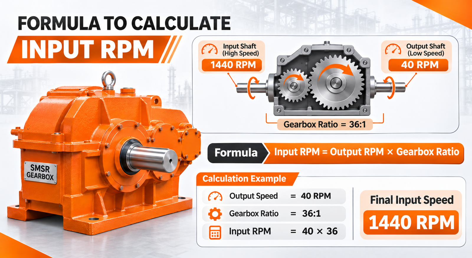
Formula to Calculate Output RPM
For example:
- Input RPM = 1500
- Gearbox Ratio = 25:1
Formula to Calculate Output RPM
How to Calculate Gearbox Ratio Step by Step
Engineers can determine the required reduction ratio using four basic steps.
Step 1 – Identify the Input RPM
First, identify the motor speed supplied to the gearbox.
Check:
- Motor nameplate.
- Manufacturer’s technical datasheet.
- Actual motor operating speed.
- Speed measurement using a suitable tachometer.
For an induction motor, actual operating speed can differ from synchronous speed because of slip.
When a variable-frequency drive is used, consider the motor’s expected operating frequency and corresponding speed.
Gearbox selection also plays an important role in heavy-duty industries. Read our guide on How Industrial Gearboxes for Cement Industry Applications Improve Efficiency to understand gearbox applications in cement manufacturing.
Step 2 – Determine the Required Output RPM
Identify the rotational speed required by the driven machine.
For example, a conveyor drive pulley may need to rotate at 60 RPM to achieve a particular belt speed.
The required pulley speed depends on the conveyor belt speed, effective pulley diameter, and drive arrangement.
Step 3 – Apply the Gearbox Ratio Formula
Assume:
- Input speed = 1440 RPM.
- Required output speed = 60 RPM.
Apply the formula:
Step 4 – Verify the Calculated Gearbox Ratio
The calculated value is a starting point, not a complete gearbox selection decision.
Before selecting a gearbox, verify:
- Available manufacturer-rated reduction ratios.
- Required output torque.
- Motor power.
- Service factor.
- Permitted input and output speeds.
- Duty cycle.
- Mounting configuration.
- Shaft dimensions and mechanical compatibility.
For an industrial application, the selected gearbox must satisfy both the speed requirement and the mechanical load requirements.
How to Calculate Gearbox Output RPM
Gearbox output RPM indicates how quickly the output shaft rotates after the input speed has been reduced.
The standard relationship is:
Example 1 – Calculating Output RPM with a 10:1 Gearbox
Gearbox output RPM indicates how quickly the output shaft rotates after the input speed has been reduced.
The standard relationship is:
Example 2 – Calculating Output RPM with a 20:1 Gearbox
Assume:
- Input RPM = 1440.
- Gearbox ratio = 20:1.
Calculation:
Example 3 – Calculating Gearbox Ratio from Input and Output RPM
Assume:
- Input RPM = 1440.
- Required output RPM = 60.
Calculation:
How Does Gearbox Ratio Affect Output Torque?
A reduction gearbox affects both rotational speed and torque.
When rotational speed decreases, the available output torque generally increases, assuming the gearbox transmits the input power with some mechanical losses.
This relationship is important for conveyor systems, crushers, and material-handling machinery that require sufficient turning force to operate under load.
Relationship Between Gear Ratio and Torque
For an ideal gearbox:
Where:
- Tout = Output torque in Nm.
- Tin = Input torque in Nm.
- i = Reduction ratio.
For example, assume:
- Input torque = 20 Nm.
- Gearbox ratio = 10:1.
Calculation:
Actual Output Torque and Gearbox Efficiency
Real gearboxes experience mechanical losses caused by friction, gear meshing, bearings, lubrication, and other operating factors.
Therefore, actual output torque is generally lower than the ideal calculated value.
The simplified efficiency-adjusted formula is:
Where represents gearbox efficiency as a decimal.
Practical calculation example:
Assume:
- Input torque = 30 Nm.
- Gearbox ratio = 20:1.
- Assumed gearbox efficiency = 90% or 0.90.
Calculation:
The estimated output torque is 540 Nm under these hypothetical assumptions.
Actual gearbox efficiency must be obtained from the manufacturer’s technical documentation for the relevant operating conditions.
Understanding the Mechanical Power Relationship
Mechanical power is related to torque and angular speed.
Factors to Consider When Selecting the Right Gearbox Ratio
A gearbox should be selected according to the complete operating requirements of the machinery. A mathematically correct ratio does not automatically mean the gearbox is suitable.
Engineers should evaluate the following factors before making a selection.
1. Motor Speed
Motor speed determines the rotational speed supplied to the gearbox.
Check the motor’s rated RPM, actual operating speed, supply frequency, pole configuration, and speed-control arrangement.
When a variable-frequency drive is used, motor speed may change during operation, which also affects gearbox output RPM.
2. Required Output Speed
The driven machine determines the required output speed.
For example, a conveyor system may require a particular drive pulley speed to maintain its specified belt speed.
The gearbox ratio should be calculated using the motor’s expected operating speed and the machine’s required output speed.
3. Torque Requirements
Torque is the turning force required to operate machinery.
A conveyor carrying heavy materials may require greater starting and operating torque than an unloaded conveyor.
Engineers should verify the gearbox’s rated output torque and its suitability for the application.
4. Application and Duty Cycle
A gearbox operating continuously in a manufacturing plant may have different requirements from one used intermittently.
Consider:
- Operating hours.
- Start-stop frequency.
- Production cycles.
- Ambient temperature.
- Expected load variation.
The gearbox should be suitable for the intended operating conditions.
5. Gearbox Efficiency
Mechanical losses affect the power and torque available at the output shaft.
Efficiency depends on gearbox design, gear arrangement, lubrication, operating speed, and loading conditions.
Always refer to manufacturer-provided performance information instead of assuming a universal efficiency percentage.
6. Mounting and Drive Arrangement
Mechanical compatibility is essential for reliable gearbox installation.
Check:
- Input and output shaft dimensions.
- Mounting orientation.
- Motor compatibility.
- Available installation space.
- Shaft alignment.
- Radial and axial loading requirements.
For compatible conveyor applications, an SMSR gearbox may provide a suitable shaft-mounted drive arrangement.
How to Calculate Gearbox Ratio for Conveyor Systems
Conveyor systems use industrial gearboxes to reduce motor speed and provide the rotational speed required by the drive pulley.
Understanding how to calculate gearbox ratio for a conveyor involves determining the required belt speed, pulley diameter, and pulley RPM.
A typical conveyor drive system consists of an electric motor, gearbox, drive pulley, conveyor belt, and supporting mechanical components.
Bearing support is equally important in conveyor drive systems. Explore Nisuka’s Plummer Block Manufacturer in Ahmedabad page to understand its industrial bearing housing solutions.
Understanding Conveyor Motor RPM
The electric motor supplies rotational power to the gearbox.
Assume a conveyor motor operates at 1440 RPM and the drive pulley requires 60 RPM.
The theoretical reduction ratio is:
This calculation establishes the initial reduction ratio required for the conveyor drive.
Calculating Required Conveyor Drive Speed
Conveyor belt speed depends on the circumference and rotational speed of the drive pulley.
The simplified formula is:
Practical example:
Assume:
- Pulley diameter = 0.5 metres.
- Pulley speed = 60 RPM.
First, calculate the pulley circumference:
Now calculate conveyor belt speed:
The theoretical conveyor belt speed is approximately 94.25 metres per minute.
This calculation assumes negligible belt-to-pulley slip and uses the effective pulley diameter.
Selecting a Suitable Gearbox Ratio for a Conveyor
Consider a conveyor requiring a belt speed of 60 metres per minute with a drive pulley diameter of 0.4 metres.
First, calculate the required pulley RPM:
V
π × D
60
3.1416 × 0.4
Assuming the motor operates at 1440 RPM:
Role of SMSR Gearboxes in Conveyor Systems
An SMSR (Shaft Mounted Speed Reducer) is an industrial gearbox designed to mount directly onto a compatible driven shaft.
It is used in suitable applications such as:
- Belt conveyor systems.
- Material-handling machinery.
- Crushers.
- Industrial processing equipment.
- Other compatible power transmission arrangements.
Its shaft-mounted arrangement can simplify installation by reducing the need for a separate gearbox foundation, depending on the drive configuration.
Conclusion – Calculate the Right Gearbox Ratio for Your Application
Understanding how to calculate Gearbox Ratio is essential for selecting a suitable industrial drive system. The relationship between input RPM and output RPM helps engineers determine the required speed reduction and achieve the desired machine operating speed.
However, gearbox selection should not depend on RPM alone. Output torque, motor power, gearbox efficiency, load characteristics, service factor, duty cycle, and mounting compatibility must also be evaluated.
For conveyor applications, calculating the correct reduction ratio helps match motor speed with the required drive pulley speed and conveyor belt movement. SMSR gearboxes can provide a suitable solution for compatible shaft-mounted conveyor drive arrangements.
Nisuka Industries offers SMSR gearboxes and related industrial conveyor components. Explore its SMSR Gearbox range and Power Plus gearbox range to review its published product information.
For application-related enquiries, contact Nisuka Industries to discuss your conveyor drive requirements and identify a suitable gearbox configuration based on your operating conditions.
FAQS
1. How do you calculate gearbox ratio?
Divide the gearbox input RPM by its output RPM. For example, if the input speed is 1440 RPM and the output speed is 72 RPM, the reduction ratio is 20:1.
2. What is a gearbox ratio?
A gearbox ratio represents the relationship between the rotational speed of the input shaft and output shaft. It determines how much the gearbox reduces or changes the motor’s rotational speed.
3. Which gearbox ratio is suitable for a conveyor system?
The suitable ratio depends on motor speed, required belt speed, pulley diameter, conveyor load, and torque requirements. Calculate the required pulley RPM first, then determine the reduction ratio and verify the gearbox’s technical ratings.
4. How does gearbox ratio affect torque?
A higher reduction ratio generally increases output torque while reducing rotational speed. Actual output torque depends on input torque, gearbox ratio, and transmission efficiency.